Logic Design for Array-Based Circuitsby Donnamaie E. WhiteCopyright © 1996, 2001, 2002 Donnamaie E. White |
|||||||||||||||||||||||||||||||||||||||||||||||||||||||||||||||||||||||||||||||||||||||||||||||||||
|
Case Study: Sizing A DesignLast Edit July 22, 2001 REVIEW OF SIZE - SECOND PASS The revised estimate (one version of the solution) shows the circuit requirements as they are now understood. Table A-3 Second Sizing Estimates Number of Cells Required
TOTAL I/O CELLS REQUIRED 162
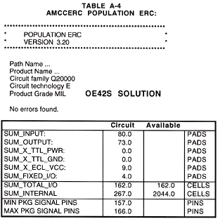
TOTAL L CELLS REQUIRED 267 Change OE42S to OE11S and delete the 2 GT87Ds. This fits into the Q20080 array that has 162 I/O cells and 2044 L cells. This is a severely I/O-bound design (of course!). A design is either core-limited or I/O limited. Note: When vectors are written for this array, they should be designed so that no more than 16-32 of the outputs switch at any one time. These are AMCC-specific vector design rules. Table A-4 AMCCERC Population ERC
PACKAGE SIZE The minimum number of signal pins that should be available on a package for this circuit is 157 (162 signals plus the 4 fixed signals minus the 9 added grounds). The worst-case number of signal pins that could be required on a package for this circuit is 166 (162 signals plus the 4 fixed signals). The truth is in the middle and is placement-dependent. PROBLEMS
ALTERNATIVE SOLUTION The differential output OE14S could be used in place of two OE42S macros
and the GT87D driver (at least one) could be deleted. This reduces the
OE42S macros from 73 to 9, and the 7 always-on enables could be driven
by a GT08L NOR gate instead of a static driver macro. The use of OE14S provides a cleaner solution (less skew) plus it frees
internal cells. The maximum frequency of the OE14S is 1.2GHz. One output
pad can be used as the true signal and the other as the compliment. Another advantage is the reduced requirement for added grounds. The 32 differential outputs count as 32 outputs and not as 64, reducing the re-quirement for this group to 8 added IEVCC, what was provided. The ninth IEVCC applies to the miscellaneous other outputs. There will be a warning issued by AMCCERC that there might not be sufficient added grounds for these miscellaneous outputs - the algorithm defined by AMCC requires that two IEVCC macros be added.
POWER The DC power dissipation for the maximum worst-case MILITARY DC power
for the OE42S version of the circuit was estimated to be over 8 Watts. Reducing the GT08S macros to GT08L macros can further reduce power.
|
||||||||||||||||||||||||||||||||||||||||||||||||||||||||||||||||||||||||||||||||||||||||||||||||||
|
Copyright @ 2001,
2002 Donnamaie E. White, White
Enterprises |
|||||||||||||||||||||||||||||||||||||||||||||||||||||||||||||||||||||||||||||||||||||||||||||||||||
