Logic Design for Array-Based Circuitsby Donnamaie E. WhiteCopyright © 1996, 2001, 2002 Donnamaie E. White |
|||||||||||||||||||||||||||||||||||
|
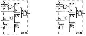
Sizing the Design - Selecting the ArrayLast Edit July 22, 2001 Dual-Function I/O MacrosEach added power and ground macro uses a pad and disables the cell that is associ ated with that pad, reducing the number of these cells and pads available for I/O operations. To offset this waste, many macro libraries include dual-function macros that use the I/O cell for one function and the pad for added ground. Silicon efficiency can be achieved with the dual function macros. The macros avail able are array series-specific and vary widely. If any of these functions applies to the design, they can reduce silicon requirements while maintaining functionality. (See Figure 3-7.) Example macros include:
Figure 3-7 Example Dual-Function I/O Macro
Example - Simultaneously Switching OutputsAll AMCC arrays, with the exception of the Q20000 Bipolar Series and the BiCMOS Q24008 array, use the following rules for adding power and ground due to simul taneously switching outputs (SSO), called an output group. Allow 8 TTL SSO outputs per quadrant, then add one TTLPWR and one TTLGND macro for each group of 1-8 after the first eight. This requires two cells, two pads and, depending on the package, two package pins. Add another pair for the next group of 1-8 and another for the next group of 1-8 and so on. All TTL output counts are converted to "equivalent" 8 mA outputs. (See Table 3-16.) For packages with internal power and ground planes, place the TTLPWR and TTLGND macros so that they are interspersed with the simultaneously switching outputs and can be bonded to the power or ground package plane. Table 3-16 Sample Rules for Adding TTL Power and Ground
Allow 8 ECL SSO outputs per quadrant, then add one ECLVCC macro for each group of 1-8 after the first eight. This requires one cell, one pad and, depending on the package, one package pin. Add another pair for the next group of 1-8 and another pair for the next group and so on. For packages with internal power and ground planes, place the ECLVCC macro so that it is interspersed with the simultaneously switching outputs and can be bonded to the power or ground package plane as required. Note that ECLVCC is a power pad in a +5V reference ECL circuit (5V REF ECL) and a ground pad in a standard reference ECL circuit. (See Table 3-17.) Table 3-17 Sample Rules for Adding ECL Power OR Ground
The Q20000 Series requires one ECLVCC per additional 1-4 ECL SSO after the first group of four. All output counts are converted to "equivalent" 50 ohm outputs. The extremely high speeds of these arrays require design procedures to ensure minimal noise. |
||||||||||||||||||||||||||||||||||
|
Copyright @ 2001,
2002 Donnamaie E. White, White
Enterprises |
|||||||||||||||||||||||||||||||||||